Gas Tightness Test Guide: Procedure & Permissible Drop

In this guide, we’ll break down what a tightness test is, how to do one step-by-step, and what counts as a permissible pressure drop according to Gas Safe and IGEM/UP/1B standards.
What Is a Gas Tightness Test?
A gas tightness test checks whether gas pipework is free from leaks and safe to use. It’s performed using a manometer (U-gauge or digital) to measure any pressure drop in the system when it’s isolated.
Tightness tests are carried out:
- On new installations or pipework, before gas is introduced.
- If a gas leak is suspected.
- After any work or modification to existing pipework.
- During routine safety inspections or landlord checks.
To carry out a gas tightness test, you either need a U-gauge (water gauge) or a digital gauge. Your flue gas analyser probably has the capability to perform a tightness test without a separate water gauge. If not, there may be an optional add-on attachment you can purchase online.

Gas Tightness Test Procedure (Step-by-Step)
Here’s how to correctly perform a gas tightness test under domestic conditions (typically following IGEM/UP/1B).
1. Preparation
-
- Check that all appliances are turned off and isolation valves are closed.
- Warn occupants that you’ll be carrying out a test and ensure good ventilation.
- Connect your manometer to the meter test point.
2. Set Test Pressure
-
- For natural gas: Apply a test pressure of 20 mbar.
- For LPG: Apply 37 mbar.
- Allow the pressure to stabilise for 1 minute before timing the test.
3. Carry Out the Test
-
- Once stabilised, start timing the test (usually 1 or 2 minutes, depending on system volume).
- Observe the pressure reading throughout the test period.
- A drop indicates a leak or expansion in the system.
4. Assess and Re-Test if Needed
-
- If the drop exceeds the permissible limit, locate and fix the leak using approved detection fluid.
- Once repaired, re-test until the result is stable.
Following this gas tightness test procedure ensures compliance with Gas Safe requirements and keeps installations safe for use.
What Is a Permissible Drop?
This is the key part of interpreting your results — understanding what’s acceptable and what’s not.
A permissible drop refers to the small pressure decrease that can occur naturally (for example, due to temperature stabilisation) and is still considered safe.
- For new installations:
➜ No pressure drop is permissible — the system must remain stable throughout the test. - For existing domestic installations with a meter, pipework, appliances, and no smell of gas, (≤ 28mm pipework), some pressure drop is allowed based on the tables below.
Gas tightness test permissible drop for domestic natural gas systems:
| Type of Installation / Meter Designation | Pipework Diameter | Maximum Permissible Pressure Drop |
| No Meter (AECV only, e.g. flat) | ≤ 28 mm | 8 mbar |
| > 28 mm ≤ 35 mm | 4 mbar | |
| Ultrasonic (≤ 6 m³/h, e.g. E6) | ≤ 28 mm | 8 mbar |
| > 28 mm ≤ 35 mm | 4 mbar | |
| Diaphragm (≤ 6 m³/h, e.g. U6, G4) | ≤ 28 mm | 4 mbar |
| > 28 mm ≤ 35 mm | 2.5 mbar | |
| Diaphragm (> 6 m³/h ≤ 16 m³/h, e.g. U16, G10) | ≤ 35 mm | 1 mbar |
Gas tightness test permissible drop for domestic LPG systems:
| Type of Installation / Meter Designation | Pipework Diameter | Maximum Permissible Pressure Drop |
| No Meter (ECV/AECV only, e.g. flat) | ≤ 35 mm | 1.5 mbar |
| Diaphragm (≤ 6 m³/h, e.g. U6, G4) | ≤ 35 mm | 1.5 mbar |
| Diaphragm (> 6 m³/h ≤ 16 m³/h, e.g. U16, G10) | ≤ 35 mm | 0.5 mbar |
If you notice a larger or continuous drop beyond these limits, it indicates a leak, and you’ll need to locate and repair it before re-testing.
Common Mistakes (and How to Avoid Them)
Even experienced engineers can make simple errors that affect results:
- Skipping stabilisation time — always allow 1 minute before timing.
- Using uncalibrated equipment — check your manometer regularly.
- Incorrect test duration — follow the guidance for system size and gas type.
- Recording errors — write down readings clearly or, better yet, log them digitally.
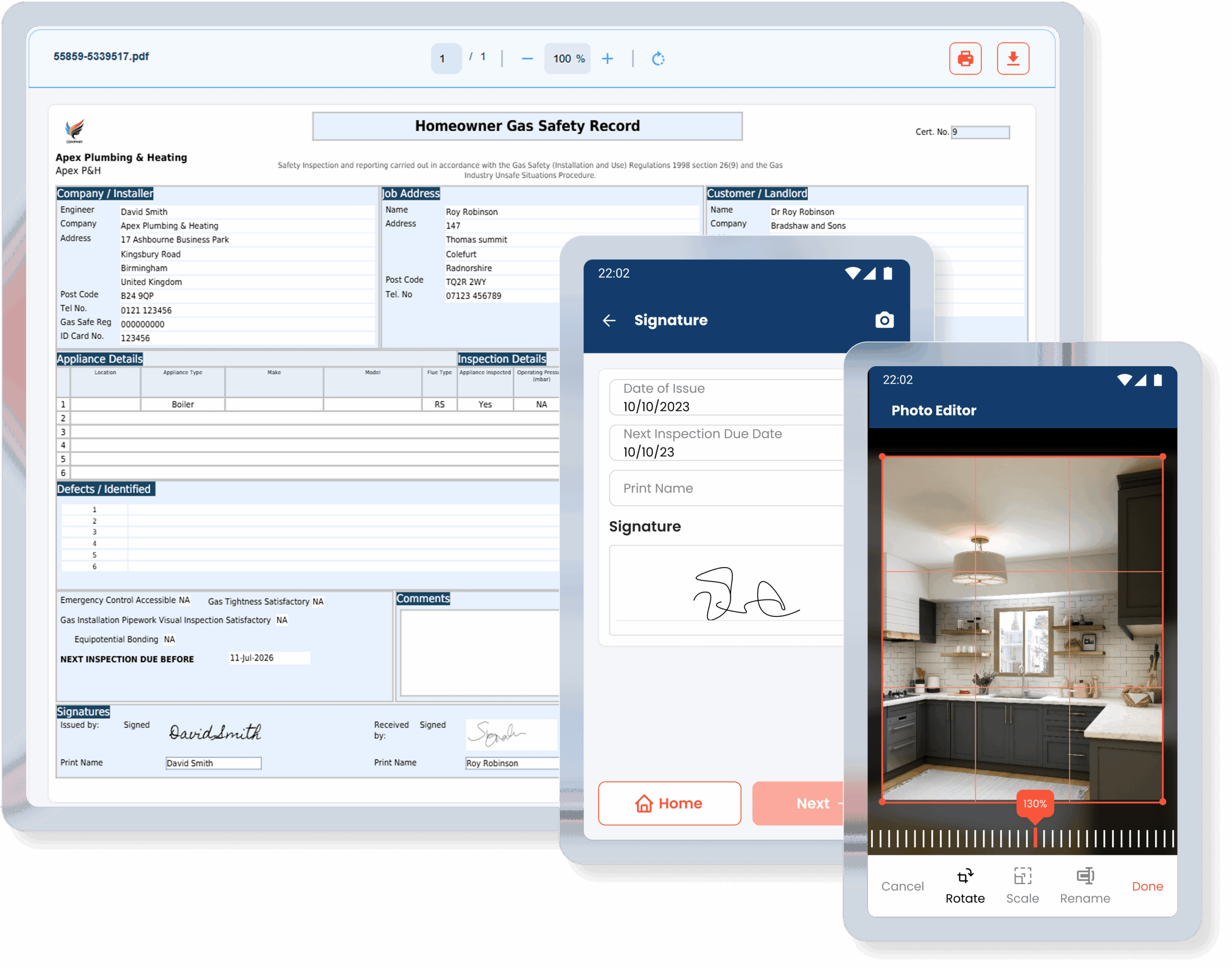
Recording results directly in your digital certificates (via Gas Engineer Software) ensures you always have a complete, traceable record linked to the job.
Recording and Certification
After completing the test:
- Record your initial and final pressures.
- Note the duration of the test and any pressure changes.
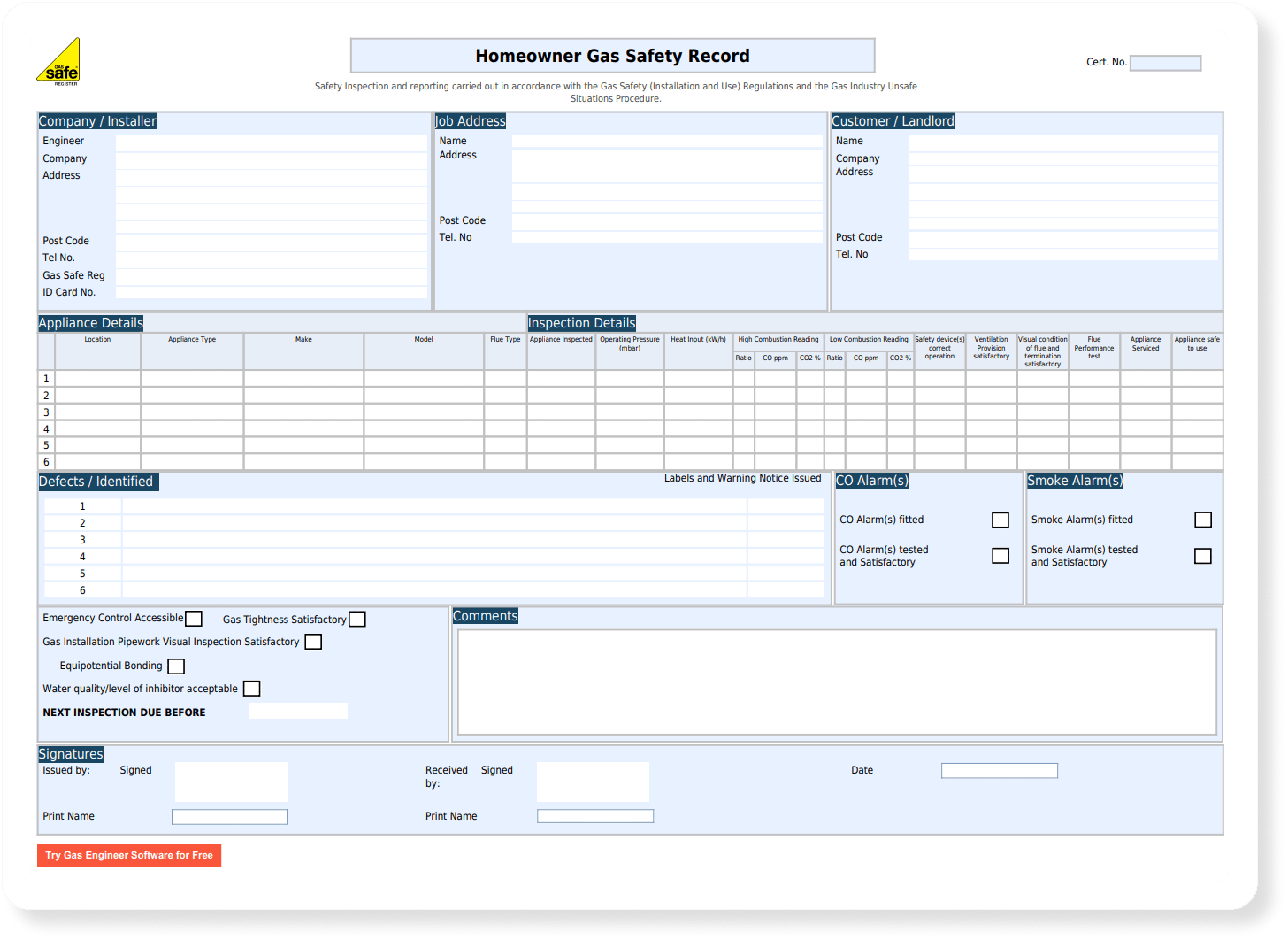
Include your name, Gas Safe number, and date of test.
If you’re using paper pads, this can be time-consuming and easy to lose. Many engineers now prefer using digital gas safety certificates, which automatically link readings to the customer record and help you stay compliant.
💡 Gas Engineer Software lets you record tightness test readings quickly on-site, generate certificates, and store them securely — no paper, no missed details, no stress.

FAQs:
What pressure should a gas tightness test be carried out at?
20 mbar for natural gas and 37 mbar for LPG (domestic systems).
How long should the test last?
Typically 1 minute for smaller systems, 2 minutes for larger ones — refer to IGEM/UP/1B for precise durations.
What’s an acceptable drop on a gas tightness test?
Up to 1 mbar for existing pipework; no drop for new installations.
Can I use a digital manometer?
Yes — as long as it’s calibrated and approved for use in gas testing. Your flue gas analyser most likely has one built-in.

